Headlamp Alignment for Tractors: How to Adjust Your Beam Correctly
In this guide
- What Headlamp Alignment Means
- Why Tractor Headlamps Lose Alignment
- UK Legal Requirements for Tractor Headlamp Aim
- Equipment and Conditions for the Wall Test
- Step-by-Step Wall Test Procedure
- Locating and Turning the Adjustment Screws
- Aim Differences Between Halogen, LED and Sealed Beam
- The MOT Beam Setter and What It Checks
- Related Articles
Tractor headlamp alignment is the angle at which the dipped beam is aimed relative to the road surface. Correct alignment puts the bright hot spot of the dipped beam onto the road 25 to 40 metres ahead of the tractor, keeps the cut-off line below the horizontal, and prevents the beam from dazzling oncoming drivers. Tractor headlamps drift out of alignment as the tractor flexes, the bonnet shifts, the suspension settles or after a lamp replacement. This guide covers the UK legal requirements, the wall test procedure, the adjustment screw locations on common tractor headlamps, and the MOT beam setter check that proves alignment is correct.
What Headlamp Alignment Means
Headlamp alignment is the vertical and horizontal angle of the dipped beam pattern relative to the tractor body and the road surface. The vertical angle controls how far down the beam points. The horizontal angle controls whether the beam points straight ahead or off to one side.
A correctly aligned dipped beam shows a flat cut-off line on a vertical surface, with the bright hot spot sitting just below the cut-off and the bulk of the light below the line. The hot spot lands on the road 25 to 40 metres ahead of a tractor running at normal headlamp height (1.2 to 1.6 m above ground). Light that crosses above the cut-off line is light that dazzles oncoming traffic.
A misaligned headlamp shows one of three faults. A beam aimed too high throws light into oncoming drivers’ eyes and into bedroom windows on village roads. A beam aimed too low cuts off forward visibility to 10 to 15 metres and leaves the driver running into darkness. A beam aimed sideways throws the hot spot into the verge or into the oncoming lane.
The standard UK convention sets the dipped beam vertical aim at 1.0% to 2.0% downward drop measured at 10 metres. A 1.5% setting means the beam drops 15 cm over 10 m of distance. This is a typical figure at tractor headlamp heights; always check the maker’s figure in the operator’s or service manual. The MOT inspection manual sets the acceptable range for cars and vans by headlamp mounting height.
Why Tractor Headlamps Lose Alignment
Tractor headlamps lose alignment for four main reasons: vibration loosens the adjusters, the bonnet or grille panel shifts, the suspension or tyres change ride height, or a lamp gets replaced without re-checking the aim.
Vibration is the biggest single cause. A tractor engine running at 2,200 rpm with a transport trailer behind shakes the headlamp assemblies with a vibration profile that no passenger car ever sees. The adjustment screws, often plain steel threads turning in a moulded plastic socket, work loose over time. The aim drifts up or to the side and the driver does not notice until oncoming flashes start.
Panel shift is the second cause. A bonnet that has been opened and closed thousands of times, struck by a low branch or pushed by a calf, sits a few millimetres out of its factory position. The headlamps move with the bonnet and the aim shifts.
Ride height change is the third cause. Worn front-axle tyres lower the front of the tractor. New rear tyres lift the back. A front-mounted weight package or a heavy implement on the front linkage drops the nose under the load. Each of these tilts the headlamp aim. A tractor that runs with a permanent front weight pack should have its headlamps aimed with the weight pack fitted.
Lamp replacement is the fourth cause. A new headlamp assembly bolts in at slightly different angles to the unit it replaces. A new H4 bulb in an old reflector sits a fraction differently from the bulb it replaces. The wall test is what proves the aim after a replacement.
UK Legal Requirements for Tractor Headlamp Aim
UK law requires a road-going tractor that must carry headlamps to have a dipped beam that does not dazzle other road users. The legal framework sits in the Road Vehicles Lighting Regulations 1989 (Statutory Instrument 1989/1796). Regulation 23 requires lamps to be kept in good working order, and regulation 27 makes it an offence to use a headlamp so as to cause undue dazzle or discomfort to other road users. Vehicles that need an MOT or goods vehicle test also have their headlamp aim checked at the test.
The Road Vehicles Lighting Regulations require motor vehicles to be fitted with dipped-beam headlamps (vehicles with a maximum speed of 15 mph or less are exempt), and the dipped beam must not dazzle another person using the road. The wording does not state a specific aim angle. On vehicles that are tested, compliance is judged at the test using the beam-setter machine.
The MOT inspection manual sets the pass criteria for headlamp aim. Cars, vans, pickups and 4x4s used on the farm (Class 4) are checked against beam-setter tolerances published in the manual. Tractors taxed in the agricultural class and used solely for agriculture, horticulture or forestry need no MOT in Great Britain; tractors in other tax classes that can exceed 40 km/h, or that haul goods more than 15 miles from base, need a goods vehicle test. Where a beam-setter check applies, the aim must show a clear horizontal cut-off, the cut-off must fall within the pass band on the beam setter, and the hot spot must not sit above the horizontal datum line.
Agricultural tractors that need no MOT are still covered by the lighting regulations whenever they use the road. A dazzling headlamp is an offence under regulation 27 of the Road Vehicles Lighting Regulations regardless of test status.
The practical UK target sits at 1.0% to 2.0% drop at 10 metres for a tractor headlamp at typical mounting height. The exact figure on the beam setter depends on the headlamp mounting height above the ground, with the MOT manual giving the correction table.
Equipment and Conditions for the Wall Test
The wall test requires a flat wall, a level concrete or tarmac surface 5 to 10 metres in front of the wall, a tape measure, masking tape or chalk, and a half-tank of fuel in the tractor.
The flat wall is the screen onto which the beam is projected. A workshop wall, a barn wall or a steel building wall all work, as long as the wall is plain, light-coloured and at least 3 metres wide. A garage door also works.
The level surface in front of the wall is the line on which the tractor sits. Any slope between the tractor and the wall throws the aim out, because the test relies on the tractor sitting square to the wall at the same level. A workshop floor or a yard that has been graded to fall under 0.5% works fine.
The tape measure marks the geometry on the wall. The chalk or masking tape draws the lines. A 5 m or 10 m measuring tape covers the standoff distance. A half-tank of fuel sets the tractor at the loaded ride height the headlamps see in normal use. A full tank pushes the nose down slightly. An empty tank lifts the nose. Half is the working average.
Tyre pressures must match the manufacturer’s road-use figures. Under-inflated front tyres drop the nose and tilt the beam down. Over-inflated rears lift the back and tilt the beam down. A tractor with a front weight pack fitted should be tested with the pack fitted. A tractor that runs a front-end loader should be tested with the loader at its road-transport position.
Step-by-Step Wall Test Procedure
The wall test follows seven steps from setup to adjustment.
- Park the tractor 5 metres in front of the wall, square on, with the tyres set to road pressure and the half-tank fuel level confirmed.
- Measure the centre height of each headlamp above the ground. Mark this height on the wall directly in front of each lamp with chalk or tape. This gives two horizontal datum marks that match the lamp centres.
- Drop a vertical chalk line from each datum mark to the floor. Mark the tractor centreline on the wall by sighting from the bonnet badge to the wall and marking the point.
- Measure 50 mm down from each headlamp datum mark on the wall and draw a horizontal line across both lamp positions. This is the dipped beam cut-off line for a 5 m standoff (a 1.0% drop equals 50 mm over 5 m). For a 10 m standoff the line drops 100 mm.
- Switch on the dipped beam. The cut-off line of each headlamp beam should align with the chalk line drawn at step 4. The bright hot spot should sit just below the line. The brightest part of the beam should sit on the centreline or slightly to the nearside of centre (UK convention dips the beam to the left).
- If the cut-off sits above the line, turn the vertical adjustment screw to lower the beam. If the cut-off sits below the line, raise the beam. If the hot spot sits off to the offside, turn the horizontal adjustment screw to bring it back to centre or to the nearside.
- Recheck after each adjustment. The screws on most tractor headlamps move the beam a few centimetres per turn at the wall. Small adjustments give large changes at 25 m road distance.
The same procedure runs at 10 m standoff. The wall geometry doubles: the cut-off line drops 100 mm at 1.0% or 200 mm at 2.0%. A 10 m test gives a more sensitive reading because small aim errors show up bigger on the wall.
Locating and Turning the Adjustment Screws
Adjustment screws sit on the back or side of the headlamp housing. The screw arrangement varies by tractor make and headlamp type.
Modern composite tractor headlamps (John Deere 6R, 7R and 8R series from 2010 onwards, Massey 6700S, 7700S and 8S series, New Holland T6 and T7 ranges, Case IH Maxxum, Puma and Magnum series, Fendt 700 and 900 Vario series) carry two Phillips or hex screws on each lamp. The screws sit behind the lamp inside the bonnet aperture or accessed through a service hatch in the wheel arch. One screw moves the beam up and down. The other moves it left and right.
Older composite headlamps (John Deere 3050 to 3950, Massey 300, 600 and 6100 series, Ford TW and 40 series, Case 685 to 956XL, Deutz DX series) carry the same two-screw arrangement, usually as 4 mm hex socket screws on the rear of the lamp.
Sealed beam units on classic tractors (John Deere 4020, 4430, 4640, Massey 135, 165, 175, 290, Ford 4000, 5000, 6610, International Harvester 574, 674, 684, David Brown 880, 990, 1212) sit inside a retaining ring secured by three or four screws around the bezel. The bezel screws hold the lamp in place but are not the aim adjusters. The aim is set by loosening the bezel ring and tilting the lamp inside, then re-tightening. A few tractors of this era carry a separate adjustment bracket behind the headlamp shell with a single screw that tilts the whole unit.
Quad-headlamp tractors (Massey 1100 series, Ford TW series with optional twin pack, John Deere 4640 with auxiliary pods) take two adjustment passes: aim the outer dipped-plus-main lamps first, then aim the inner main-only lamps to point further ahead, with the hot spots overlapping at 60 to 80 m road distance.
LED retrofit units in old housings adjust via the same screws as the original unit. The retrofit lamp body bolts into the original bezel and moves with it. The cut-off pattern on an LED retrofit is sharper than the original halogen pattern, which makes the wall test easier to read.
Aim Differences Between Halogen, LED and Sealed Beam
Halogen, LED and sealed beam tractor headlamps each produce a slightly different beam pattern, which changes how the wall test reads.
Halogen headlamps with an H4 bulb in a composite reflector produce a beam with a gradual cut-off, a soft transition from light to dark across about 50 mm of vertical band, and a hot spot that sits 40 to 80 mm below the cut-off centreline. The hot spot is bright but not laser-sharp. Aim is set by putting the bottom of the soft cut-off band onto the chalk line, not the top.
LED headlamps and LED retrofit conversions produce a sharper cut-off, with the transition from light to dark happening across 10 to 20 mm. The hot spot sits closer to the cut-off line, often only 20 to 40 mm below. The sharp pattern makes wall reading easier but also makes any aim error more visible to oncoming drivers. LED conversions in old housings often need re-aiming after the first conversion because the new chip placement changes the beam relative to the original bulb position.
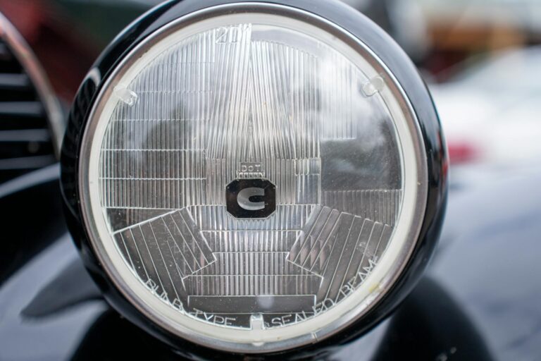
Sealed beam units produce a beam pattern set by lens prisms, with a moderately soft cut-off and a hot spot that sits 60 to 100 mm below the cut-off centreline at 10 m. A 7-inch round Type 2 sealed beam (the standard agricultural size) carries factory prisms that set the dipped pattern, and the aim sets the position of the whole pattern on the wall.
Xenon HID headlamps (rare on tractors, more common on high-end self-propelled sprayers and combines) produce the sharpest cut-off and the highest hot spot intensity. On cars, HID headlamps must have automatic levelling and headlamp cleaning; tractors are approved under different installation rules, so check the tractor maker’s data. Manual aim with a wall test still applies.
The colour temperature does not change the aim procedure. The cut-off line position is the same whether the bulb is a warm halogen yellow or a daylight LED white.
The MOT Beam Setter and What It Checks
The MOT beam setter is a wheeled optical instrument the tester rolls in front of each headlamp during the lighting check, and it confirms the aim falls within the pass tolerances published in the MOT manual.
The beam setter sits on a flat trolley with an aiming optic at headlamp height. The tester lines the optic up with the lamp, switches on the dipped beam, and reads the cut-off position on a screen inside the optic. The screen shows a grid of pass lines. The cut-off must fall within the pass band on the grid, must show a clear horizontal segment, and must show the correct nearside upturn (the kink in the cut-off that throws extra light onto the verge).
The MOT manual sets the pass tolerances by headlamp mounting height. A headlamp mounted at 800 mm above the ground passes within a different band from a headlamp mounted at 1,400 mm. The tester reads the mounting height, looks up the band, and checks the beam against it.
A fail at MOT means one of three things: the cut-off is too high (dazzles other road users), the cut-off is too low (insufficient forward illumination), or the cut-off is missing or wrong shape (faulty bulb, wrong bulb fitted, or damaged reflector). The first two faults are aim faults and clear with screw adjustment. The third fault needs a bulb or lamp replacement.
A wall-test aim that matches the MOT beam-setter tolerance is the same aim that passes at MOT. A vehicle checked at home with the 5 m or 10 m wall test does not need a separate beam-setter check before its test, although a garage with a beam setter can confirm the aim in a minute or two.
Agricultural tractors that need no MOT never face the beam setter, but the same duty not to dazzle applies under regulation 27 of the Road Vehicles Lighting Regulations. A dazzling beam is an offence, which can lead to a fixed penalty or prosecution, whether the vehicle is MOT-exempt or not.
Related Articles
- The tractor headlights guide covers all tractor headlamp types and selection.
- Halogen headlamp bulb types explains H1, H3, H4 and H7 bulbs used in tractor lamps.
- LED headlamp conversions covers the LED retrofit route and the impact on aim.
- Sealed beam headlights covers classic tractor sealed beam units and adjustment.
- Tractor lighting regulations UK sets out the wider road-legal framework.
- Road Vehicles Lighting Regulations is the primary legislation reference.
- Shop the full range of tractor headlamps for replacement and LED upgrade units.